Table Of Content

With \(F(s)\) being the prototype analog filter transfer function similar to that for the Chebyshev filter. \(G(\omega)\) is a rational function that approximates zero in the passband and infinity in the stopband. The definition of this function is a generalization of the definition of the Chebyshev polynomial.
Filter Implementation: Analog or Digital?
Eaton's UM 15 Mobile Filter Unit for Hydraulic Systems - Machine Design
Eaton's UM 15 Mobile Filter Unit for Hydraulic Systems.
Posted: Thu, 04 Apr 2024 07:00:00 GMT [source]
The matched-passband and matched-both designs have a ripple of exactly 1 dB at the passband frequency value of 100 Hz. The FIR Equiripple filter has a Density Factor option which controls the density of the frequency grid. Increasing the value creates a filter which more closely approximates an ideal equiripple filter, but more time is required as the computation increases.
The impulse response

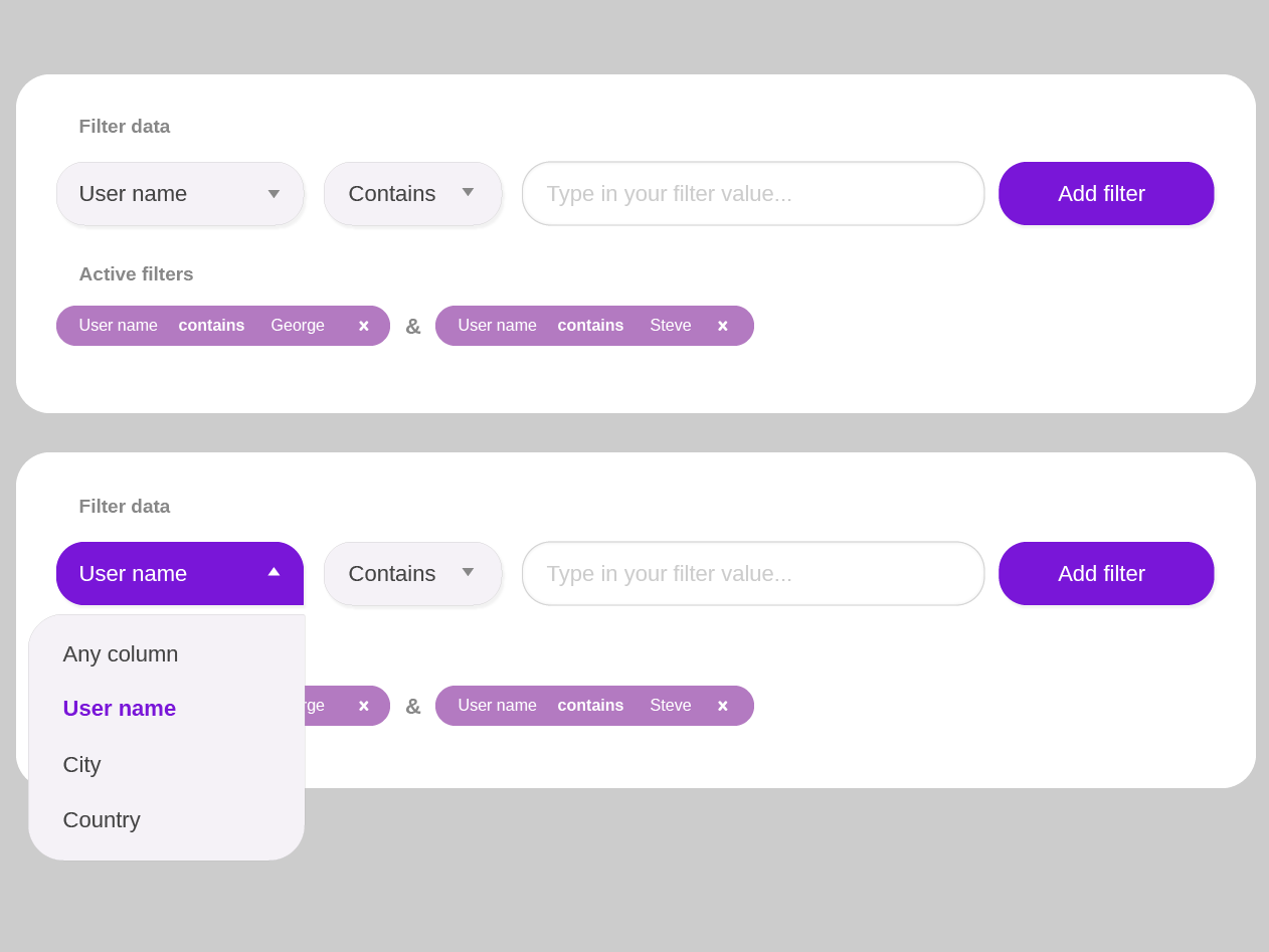
These options don’t have to be displayed in their full height, but can live in a larger scrollable pane. This range of options doesn’t have to fit on a single screen, or be displayed on a single page, or be limited to a small shortlist that we can easily remember. It can be anything from dozens to hundreds of items scattered over a number of pages. We will now explore an alternative method for the realization of the second-order filter section. The remaining task is to realize the Butterworth and Chebyshev filters which were specified at the beginning of the tutorial discussion.
Bandpass Filters: Navigating the Frequency Spectrum
The art of filter design necessitates compromises with respect to cutoff and roll off. They are the image parameter method, insertion loss method, and numerical synthesis. The image parameter method is an old and crude method, whereas the numerical method of synthesis is newer but cumbersome. The insertion loss method of filter design on the other hand is the optimum and more popular method for higher frequency applications. Digital filter implementation involves using digital signal processing techniques to achieve the desired filter characteristics.
As you can see in the Current Filter Information area, the filter order decreased from 30 to 16, the number of ripples decreased and the transition width became wider. The passband and the stopband specifications still meet the design criteria. Another issue related to computational complexity is separability, that is, if and how a filter can be written as a convolution of two or more simpler filters. In particular, this issue is of importance for multidimensional filters, e.g., 2D filter which are used in image processing. A result of the filter design process may, e.g., be to approximate some desired filter as a separable filter or as a sum of separable filters.
A first-order recursive filter will only have a single frequency-dependent component. This means that the slope of the frequency response is limited to 6 dB per octave. Filter design is the process of designing a signal processing filter that satisfies a set of requirements, some of which may be conflicting. The purpose is to find a realization of the filter that meets each of the requirements to a sufficient degree to make it useful.
In fact, for every interface, and for every intent, we have a particular comfortable range in mind, that is a preferred number of options that we think we can manage relatively effortlessly. As customers, we use filters to reduce a large set of options to a more manageable and highly relevant selection. Perhaps just a few dozens of payment slips instead of thousands, or just a handful of blouses rather than the entire collection.
Simultaneous optimization in both domains
The issues that we’ve explored in the article apply equally to large and small screens. However, on small screens, and especially on slow connections, these issues become even more critical. Most of the time, interfaces tend to block the entire UI on a single filter input, causing massive delays for customers on the go (e.g. Crutchfield, Walgreens). On the other hand, it’s common to split the screen to display a filters overlay, while still showing the product list updated in the background (e.g. Nordstrom).
Advancements in filter design have led to the development of complex and specialized filter topologies that offer enhanced performance. These topologies include elliptic filters, high-order Butterworth filters, and active filter designs utilizing advanced op-amp configurations. By exploring these advanced filter topologies, designers can push the boundaries of filter performance in terms of passband ripple, stopband attenuation, and selectivity. One common method for designing FIR filters is the Parks-McClellan filter design algorithm, based on the Remez exchange algorithm.
After setting the design specifications, click the Design Filter button at the bottom of the GUI to design the filter. Add markers to the -3dB bandwidth points to determine the lower and upper cutoff frequencies. That is because the passband ripple varies between approximately -1.0 dB and -1.5 dB, which will slightly impact the definition of the lower and upper cutoff frequencies. Now that the parameters have been determined, create a model of the distributed bandpass filter in a new layout window. Use the MCFIL components for the coupled line sections and the MLIN components for the 50 Ω lines.
If this is not acceptable then the design can be reexamined with the idea of using 1% tolerance component values. The detailed study of the changes in the shape of the filter response curve can be done using a computer simulation program such as PsPice. The simulation can also be useful for determining the effect of the non-ideality of the Op-Amp on the frequency response. It is not necessary to go through the computation mentioned above, as extensive tables of most transfer functions are available in the literature.
We therefore have some latitude in our design to compensate for tolerances of component values. When it comes to manufacturing RF filters, factors such as cost, scalability, and repeatability become important considerations. The chosen manufacturing process should be capable of producing filters with consistent performance and minimal variation.
This is done by choosing a narrow ideal filter impulse response function, e.g., an impulse, and a weighting function which grows fast with the distance from the origin, e.g., the distance squared. An important parameter is the relative strength of the two weighting functions which determines in which domain it is more important to have a good fit relative to the ideal function. As stated by the Gabor limit, an uncertainty principle, the product of the width of the frequency function and the width of the impulse response cannot be smaller than a specific constant. This implies that if a specific frequency function is requested, corresponding to a specific frequency width, the minimum width of the filter in the signal domain is set.
Once the interfering frequencies are identified, the notch filter can be designed to target and suppress those frequencies while allowing the desired frequencies to pass through unaffected. The result of the design is that for any three of the parameters given, the fourth is minimum. This is a very flexible and powerful description of a filter frequency response.
Design a minimum-order Chebyshev Type II filter with the same specifications as in the previous examples. You can use the info function to get information about the parameters used to design the filter. FIR filters are very attractive because they are inherently stable and can be designed to have linear phase. Nonetheless, these filters can have long transient responses and might prove computationally expensive in certain applications. The Targets menu of Filter Designer allows you to generate various types of code representing your filter.
Sometimes filters appear in a drop-down overlay, and sometimes as a pill below the filters. But most of the time, unlike previous examples, when a filter is selected, it displays a sidebar mega-filter-overlay on the right with all available filtering options grouped there. As the customer is making their way through the filters, the product list is updated in the background asynchronously. More importantly, notice the “Apply” button which label changes depending on the input. In this example from Dell.com, as you choose your laptop features, only a single input is registered at a time.


No comments:
Post a Comment